fiber optic fault rectification
How to Identify the Fiber Optic Link Problems ?
Fiber optic networks are designed for continuous operation. Often, fiber optic networks work to their optimum efficiency. However, fiber optic link problems are sometimes faced in the networks. These fiber optic link problems are difficult to identify due to the complexity of the fiber optics networks. However, to ensure the optimum performance of fiber optic networks, it is essential to identify and resolve the problem of fiber optic links. This post discusses, the method to identify the fiber optic link problems and a few tips to resolve the same.
Methods to Identify the Fiber Optic Link Problems
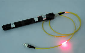
An Overview of Fiber Optic Visual Fault Locator
The following steps are taken during the identification of fiber optic link problems with the visual fault locator.
- The visual fault detector can only be used in on-field fiber optics solutions. Therefore, the first step is to test the transaction point by directing the laser pointer at the connecting location. The transaction point is where the connector is spliced to the cable. Identify the presence of external optical power, if any. If there is no external influence, test the splice connection. Check if the cable is incorrectly spliced, if not, check for the next location.
- Glide the visual fault locator through the length of the fiber cable. However, experienced fiber-optic network testers can use a logical approach to locate a potential area of the fault. Otherwise, the cable must be tested thoroughly. Across the length, one must check for fiber cuts, loss of signal strength, etc.
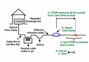
- If the loss of signal strength is identified at one location, the fiber must be tested for another 20 to 30 miles. If the signal break traces cannot be indicated with the fault locator, the use of a time-domain reflectometer may be required in extreme cases.
Tips to Resolve the Fiber Optic Link Problems
- Use appropriate and high-quality fiber optic connectors, media converters, fiber optic switches, etc.
- Opt for quality fiber splicing services in order to reduce attenuation losses.
- In the case of fiber cuts, re-cladding or replacement of fiber cable may be required.
- Source only high-quality fiber optics transmitters and receivers to sustain the signal strength for a longer duration. The transmitters must be tested for the quality of laser or LED signal emitters.
Trouble Shooting
Trouble shooting with a visual fault locator can be rewarding to any technician. They are a must have tool to closely locate nearby faults. When a test is conducted, the laser red light brightly shines round the fracture or break in optical fiber. This allows red light to escape into the cladding, fiber coatings, buffers or ultimately cable jacket. This red light allows the tech to identify the issue at hand.
Without directly looking into the laser light, technicians can verify continuity or through-put with the VFL. Simply plug into one side of the network link or cable and recognize if light is traveling to the opposite end. If the technician verifies continuity they can eliminate one potential fault of having a broken fiber. However, keep in mind although the cable with the red VFL light shows continuity, it may still have attenuation too high for the receiver to function properly, the VFL will not assist in that determination.
Utilize a visual fault locator to verify correct polarity on multi-fiber cables such as duplex patch cables. One fiber is designated transmit and other receive, if the fibers are crossed the network will not operate. Often identification of this issue can easily be corrected by switching connector positioning. Several manufacturers offer only single fiber VFLs which will require the use of patch cords and duplex mating sleeve troubleshooting LC duplex jumpers. Fiber Instrument Sales, Inc. manufactures duplex visual fault locators with features technicians desire such as duplex adapter interface and polarity toggling between A and B sides as well continuous or modulated lasers for quick identification of fiber.


