reach us
When you want to be our services
Explore
optic fiber
icon

optic fiber cable mm vs sm
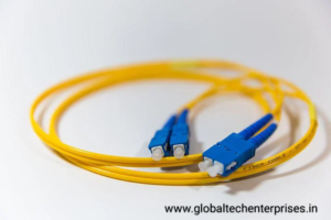
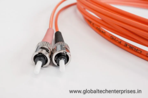
Single Mode Fiber Optical Cable VS Multimode Fiber Optical Cable
Both these types of optical fibers have their own attributes and are used as per the specific requirements. But there are distinguishing differences between both types. In the following paragraphs, we will be shedding light on what are the areas that differentiate single-mode and multimode fiber cables.As the name suggests, single-mode optical fiber is built to transmit a single light mode, and multimode fiber is designed to propagate several simultaneous light modes. But the difference between single-mode and multimode fiber does not end there. There is a major difference in their built too. Single Mode Fiber Optical Cable features a 9µm optical core. This eventually helps it with longer transmission distance and higher bandwidth. On the other hand, the optical core in a Multimode Fiber Optical Cable measures at 50µm.
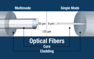
When it comes to bandwidth, both optical fiber types function differently. Single Mode Fiber Optical Cable uses strong and brighter light sources with lower attenuation. At the same time, it can deliver unlimited bandwidth, making it a preferred choice in this high-paced world.
As compared to this, Multimode Fiber Optical Cable can transmit multiple light modes. Also, the attenuation is higher, and the brightness is lower. And this is the reason why the bandwidth is limited in Multimode Fiber optical cables. Higher bandwidth is an obvious choice among users who prefer an uninterrupted experience, so the single-mode optical fiber has the upper hand over Multimode Fiber Optical Cable in this regard.
data center cabling and manegment
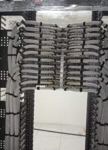
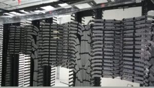
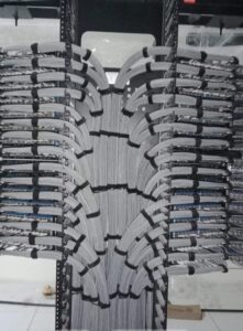
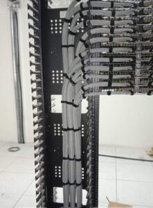
Basic Knowledge & Tips for Data center Cabling
Data Center Cabling Best Practices
Tips for Data Center Cabling Design
Before starting cabling a data center, planning the basic design for the data center is essential.
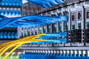
Using structured cabling—this approach to cabling includes designing cable runs and connections for better data center cable management. And compared with traditional point-to-point cabling, using structured cabling means establishing a main distribution area (MDA), one or several horizontal distribution areas (HDAs), and two-post racks for better access and cable management.
Choosing the right cabling solution—though UTP copper cable is used commonly in data center today, as mentioned above, the need for maximum and future support for higher-speed system is resulting in the installation of more fiber. Fiber optic cabling in data center is becoming a non-negligible option.
Cable routing and design—airflow and cooling issues have become a new challenge in data center cabling design. Cable routing and design can strongly influence and affect airflow design efficiency.
Planning cabling patch ways—it’s one of the most important factors to consider when cabling a data center. The key parameters that affect the cabling pathways are the rack density, type/count/diameter of cables, end equipment cable entry, and room height. All these should be paid attention to.
Data Center Cabling Standards
Industry cabling stands for data centers is to ensure safety and provide the basis for building an integrated infrastructure. At the same time, they also offer guidelines for maintaining high-levels of cable performance for the next several years. There are a number of data center standards for cabling. Here are the three common ones.
Data Center Cable Installation & Maintenance
Though fiber optic cabling has distinct benefits compared with copper cable in regard to work performance, improper practices of fiber cabling may lead to bad effect on data transmission. Therefore, we must maintain the best practices when we installing both fiber optic cable and copper cable.Pay attention to fiber bend radius. The bend radius, or measurement of a curve, can determine how strong the data signal will flow. When installing fiber patch cables, don’t bend them beyond its specified bend radius.
fiber optic fault rectification
How to Identify the Fiber Optic Link Problems ?
Fiber optic networks are designed for continuous operation. Often, fiber optic networks work to their optimum efficiency. However, fiber optic link problems are sometimes faced in the networks. These fiber optic link problems are difficult to identify due to the complexity of the fiber optics networks. However, to ensure the optimum performance of fiber optic networks, it is essential to identify and resolve the problem of fiber optic links. This post discusses, the method to identify the fiber optic link problems and a few tips to resolve the same.
Methods to Identify the Fiber Optic Link Problems
An Overview of Fiber Optic Visual Fault Locator
The following steps are taken during the identification of fiber optic link problems with the visual fault locator.
- The visual fault detector can only be used in on-field fiber optics solutions. Therefore, the first step is to test the transaction point by directing the laser pointer at the connecting location. The transaction point is where the connector is spliced to the cable. Identify the presence of external optical power, if any. If there is no external influence, test the splice connection. Check if the cable is incorrectly spliced, if not, check for the next location.
- Glide the visual fault locator through the length of the fiber cable. However, experienced fiber-optic network testers can use a logical approach to locate a potential area of the fault. Otherwise, the cable must be tested thoroughly. Across the length, one must check for fiber cuts, loss of signal strength, etc.
- If the loss of signal strength is identified at one location, the fiber must be tested for another 20 to 30 miles. If the signal break traces cannot be indicated with the fault locator, the use of a time-domain reflectometer may be required in extreme cases.
Tips to Resolve the Fiber Optic Link Problems
- Use appropriate and high-quality fiber optic connectors, media converters, fiber optic switches, etc.
- Opt for quality fiber splicing services in order to reduce attenuation losses.
- In the case of fiber cuts, re-cladding or replacement of fiber cable may be required.
- Source only high-quality fiber optics transmitters and receivers to sustain the signal strength for a longer duration. The transmitters must be tested for the quality of laser or LED signal emitters.
Trouble Shooting
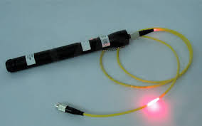
Trouble shooting with a visual fault locator can be rewarding to any technician. They are a must have tool to closely locate nearby faults. When a test is conducted, the laser red light brightly shines round the fracture or break in optical fiber. This allows red light to escape into the cladding, fiber coatings, buffers or ultimately cable jacket. This red light allows the tech to identify the issue at hand.
Without directly looking into the laser light, technicians can verify continuity or through-put with the VFL. Simply plug into one side of the network link or cable and recognize if light is traveling to the opposite end. If the technician verifies continuity they can eliminate one potential fault of having a broken fiber. However, keep in mind although the cable with the red VFL light shows continuity, it may still have attenuation too high for the receiver to function properly, the VFL will not assist in that determination.
Utilize a visual fault locator to verify correct polarity on multi-fiber cables such as duplex patch cables. One fiber is designated transmit and other receive, if the fibers are crossed the network will not operate. Often identification of this issue can easily be corrected by switching connector positioning. Several manufacturers offer only single fiber VFLs which will require the use of patch cords and duplex mating sleeve troubleshooting LC duplex jumpers. Fiber Instrument Sales, Inc. manufactures duplex visual fault locators with features technicians desire such as duplex adapter interface and polarity toggling between A and B sides as well continuous or modulated lasers for quick identification of fiber.
Underground Cable Plant
Underground Cable Plant Construction
Underground cables are pulled in conduit that is buried underground, usually 1-1.2 meters (3-4 feet) deep to reduce the likelihood of accidentally being dug up. In extreme cold climates, cables may need to be buried at greater depths where there temperatures are colder and frost penetrates to greater depths. The process usually begins with digging a trench to bury the conduit which is generally PVC plastic pipe, sometimes with pre-installed innerduct (also called duct liner) with a pulling tape to facilitate the actual cable pulling process. Directional boring can also be used to avoid digging up the surface, for example in crossing streets or sidewalks.
If the conduit and cables are all dielectric, as they usually are, a conductive marker tape should be buried above the conduit to assist in future cable location and as a warning to anyone digging in the vicinity of the cable. Conductive tape to be detectable should be no more than 300mm (12 inches) below the surface.
It’s immensely important for trenches to be excavated to such a depth that the crown of the duct has at least 800mm (32 inches) of backfill cover, in all soil conditions, except for where hard rock conditions are encountered. Where it is not possible to obtain the specified minimum trench depth, the client must be consulted.
The Secret Of A Successful Underground Fiber Optic Cable Installation
The two most common outdoor fiber optic cable installations are pole line aerial installation and underground cable installation. Underground cable installation can be buried directly underground or placed into a buried duct. Direct burial installation: |
Direct burial installations are most common for long cross-country installations. The cables are plowed in or buried in a trench; the installation process can be very quick. The most common cables used for direct burial are steel armored outdoor fiber cables.
Underground duct installation:
Fiber optic cables can also be pulled through underground ducts, which protect the cables from harsh environment. Underground duct installation also provides opportunity for future expansion without the need to dig. This is the most common practice in urban areas. Another benefit is that fiber cables without armor can be used which makes the installation even easier.
Preparation before underground cable installation:
1. Obtain proper right-of-way permits
2. Identify existing underground utilities such as buried cables, pipes
3. Investigate the soil condition in order to determine the installation depth, whether duct should be used, the type of fiber cable should be used and plowing equipment needed
Cable Burial techniques:
1. Plowed under
Plowing in a fiber cable is faster than trenched. But this process has to be carefully monitored to prevent from damaging the cable.
2. Trenched
The fiber cable can also be trenched. This process is slower than plowing in; however, it allows a much more controlled cable installation. Trenches can be dug by hand or by machine.
3. Directional boring
Directional boring technique is used where the surface cannot be worked on such as high, railway crossings, etc. Instead, a boring machine is used to bore a several inches diameter hole underneath the surface, a duct is pulling through the hole and then fiber cables pulled into the duct.
Important factors:
1. Cable installation depth: up to 40 inches
The depth that fiber cables should be buried is determined by the soil conditions and surface usage. In colder areas, fiber cables are typically buried below the frost line to prevent the cables from being damaged by ground frost heaves.
2. Keep the trenches as straight as possible
Fiber cable trenches should be straight, and the trench bottom should be flat and level. Backfill can also be used to distribute the cable load evenly and protect the cables.
3. Fiber cable warning labels should be buried directly above the cable
Fiber optic warning cables are typically buried directly above the cables to warn future digging operations. Or concrete slabs can be buried below the warning label but above the cables to provide even more protection.
4. Whenever conducting armored fiber cables are used, they should be properly grounded
In direct burial installations, steel armored fiber cables are often chosen for their strength and protection from rodent bites. A very important thing to keep in mind is to properly ground the cables. They should be grounded at all termination points, splices and building entrances. The cable steel armor should be connected to a ground wire using a compression-type clamp. The cable ground wire is then bolted to a nearby ground terminal strip.
5. Fiber optic cable minimum bending radius should always be observed during installation
data center fiber optic
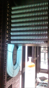
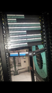
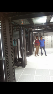
As with our previous builds, these new long-haul fiber routes will help us continue to provide fast, efficient access to the people using our products and services. We intend to allow third parties — including local and regional providers — to purchase excess capacity on our fiber. This capacity could provide additional network infrastructure to existing and emerging providers, helping them extend service to many parts of the country, and particularly in underserved rural areas near our long-haul fiber builds.
Unlike a retail telecommunications provider, we will not be providing services directly to consumers. Our goal is to support the operators that provide such services to consumers. We will reserve a portion for our own use and make the excess available to others.
penta scaning fluke testing
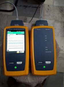
Whether installing new cable, or troubleshooting existing cable, ethernet network cable testing plays an important role in the process. Common network tests for datacom cabling include length, wiremap, attenuation, NEXT, DC loop resistance, and return loss.
As networks evolve, so do the requirements of the cabling infrastructure to support them. New network cabling standards are continuously being developed to provide guidelines for cabling professionals when installing, testing, troubleshooting, and certifying either copper and fiber cable network. Whether it’s 10BASE-T, 100BASE-TX or 1000BASE-T, there are specific requirements and potential pitfalls in implementing these technologies. With 10GBASE-T, it becomes even more critical to keep current with the latest proliferations in ethernet cabling and network cable testing.
Network cable testing provides a level of assurance that the installed cabling links provide the desired transmission capability to support the data communication desired by the users.
Network technicians, Network Managers, and System Installers need their twisted pair cabling system to reliably support Ethernet applications up to 10GBASE-T. Efficiently solving network connectivity problems, installing PoE devices, and managing network move, adds, and changes is essential in today’s fast-paced IoT centric environment. Fluke Networks Cable + Network Testers enable users to build and maintain their connected infrastructure
fiber optic cable splicing

Splicing in the field
When fiber was first deployed, it was mechanically spliced, meaning that fibers were butted together as tightly as possible and then mechanically encapsulated. Due to the potential for signal loss and poor reliability this was soon superseded by fusion splicing. This offers the best quality connection of all in-field options in that the fiber ends are lined up and welded together. No excess cable is left over when the process is complete.
However, fusion splicing is time-consuming and requires specialist labor and equipment. There is no guarantee that the splice will be successful until it is completed. Availability of specialist splice engineers can be a big problem – those that can be obtained on the open market often charge high rates. In many developing countries, trained splicers and jointers are in such short supply that it is unfeasible to use them for a project of any size. However, for the very largest telcos who have invested heavily in training and equipment fusion splicing, field-termination can make financial sense.
optic fiber cable
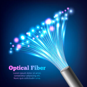
What is Optic Fibre Cable Used for?
Fiber optic cables can carry enormous volumes of data at very high speeds. For this reason, fiber optic technology serves various purposes.
High-speed Internet
Fiber optic cables are less bulky, lighter, more flexible, and carry more data as compared to copper cables
Networking
Whether it is between computers within a building or across the buildings, fiber optic cable is always a preferred mode for faster networking.
Data centres
It is used for connecting edge data centers or for structured cabling within the data centres as well.
Defence application
Very high level of data security is required within military and aerospace applications. Fibre optic cables offer the ideal solution for data transmission in the defence sector.
OTDR
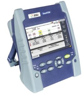
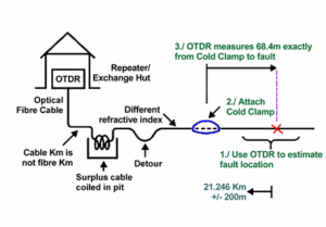
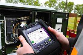 An OTDR is the optical equivalent of an electronic time domain reflectometer. It injects a series of optical pulses into the fiber under test and extracts, from the same end of the fiber, light that is scattered (Rayleigh backscatter) or reflected back from points along the fiber.


